

Table of contents
Introduction to different types of bolt tightening methods
This article aims to provide a state-of-the-art overview in the field of industrial bolt tightening and bolted connections. Following a comprehensive review of current bolt tightening methods, we will examine how TRAXX products and services offer an innovative solution for measuring the tightening tension of complex threaded assemblies.
What is a screw?
Screws are ubiquitous: in a stapler, a bed frame, a car engine, and even in Atlas V rockets. A bed frame coming apart is one thing, but a Atlas V rocket launcher detaching in flight is another. The problem is clear: it’s not just about tightening, but knowing how to tighten correctly. First and foremost, we will attempt to understand the function of a screw and its operational mechanism. To join two pieces, we compress them together using bolts, thereby introducing a compressive force between them. By turning the nut, thanks to the helical thread of the screw, the nut moves closer to the head of the screw, thereby compressing the two pieces. The screw itself elongates under the tightening effect. Yes, a screw changes its state, elongating like an elastic when subjected to tensile force via the nut. Imagine an elastic stretched between two fingers. The compressive force bringing your fingers together results from the tensile force within the elastic, which tends to return to its normal shape.
Similarly, in a bolted assembly, the screw seeks to return to its initial, relaxed state. The tensile force within the screw is equivalent to the compressive force applied between the assembled parts. To quantify this force, we use the unit Newton. The tightening force of a bed frame differs significantly from that of an Ariane 5: in the latter, the forces involved are colossal. For instance, a bolt in an automotive engine cylinder head can withstand a load of 5 tons, which equals a force of 50 kN. If the bolt experiences a force of 5 tons, the parts are compressed by an equivalent force. Thus, we understand that tightening a bolt involves the application of a measurable force. In industrial terms, this is referred to as “tightening tension.”
In summary, the screw is under tension while the threaded assembly is under compression. But how do you tighten a screw correctly? There are various methods and techniques for bolt tightening, each varying in effectiveness.
Types of bolt tightening methods
So how do you tighten a bolt?
The first answer that often comes to mind is: “Just turn it!” This approach, ingrained in our habits for centuries, relies on the circular motion of rotation when thinking about a bolt. However, this is not the only effective method.
In the industrial context, we refer to the application of torque.

The well-known bolt tightening method: Torque
Torque tightening involves applying two opposing forces, forming what is known as a torque force. But what exactly is torque? It’s a force applied at a certain distance from a pivot point. When tightening, how far should we go? Until resistance is noticeable? Before the material breaks? This approach is imprecise.
The tools used for this method vary: a screwdriver for common applications and a torque wrench in industry, the latter measuring the applied torque. The method operates on the principle that applying a force of 200 N at a distance of 0.5 m equals a torque of 100 N·m (200 x 0.5). This method is the most commonly used in industry.
For reference, the first torque wrench was invented in 1916, making it a century-old practice.

Despite its widespread acceptance and use, this method carries significant uncertainty. Why? What happens? Let’s conduct an experiment: take several screws and tighten them all to the same torque using a torque wrench. Then, measure the tension achieved in each of these screws (we will discuss how to do this later). Common sense suggests that the tension will be the same for all screws, but this is not the case. In reality, for a given torque, we observe an uncertainty of ±50% in the tension achieved.
Most engineering offices establish correlation tables between the applied torque and the theoretically obtained tension, based on various calculations, including those using finite element analysis (FEA).
These tables are referred to as torque tightening tables.
This practice is flawed because it does not account for the inherent uncertainties in the torque tightening method.

For example, let’s take an M10 bolt (10 mm diameter). If you apply a torque of 46 N·m, you would theoretically achieve a tension value of 24.275 kN, assuming an average friction coefficient of 0.15. This is how these tables typically function.
However, to create these tables, engineering offices assume that the friction coefficient is known. The friction coefficient, a dimensionless number ranging from 0 to 1, represents the resistance to relative motion between two contacting surfaces. In our case, these surfaces include the bolt, the nut, and the parts being tightened. Assuming this friction can be precisely measured and reduced to a single figure is unrealistic.
In reality, there are frictional interactions under the bolt head, between the parts being tightened, along the threads of the bolt and nut, and within the tapped hole. All these components, being products of industrial manufacturing, contain imperfections that influence friction in random ways. In practice, during the tightening of a bolt, countless frictional interactions occur, making precise measurement or calculation impractical. Friction coefficients are therefore variable and cannot be precisely measured.
Thus, these tables rely on numerous approximations, despite presenting values with a precision of five decimal places, which can be misleading. They should no longer be used.
Otherwise, it should not come as a surprise to find some bolts tightened three times more than others on an engine block where uniform tightening should be expected.
Torque and angle bolt tightening method
This bolt tightening method, although similar to the torque-only method, is more effective. It operates on the principle that turning the nut one full revolution (360 degrees) equals advancing the bolt thread pitch. If the bolt pitch (expressed in millimeters) is known, we can determine how much the bolt elongates.
The method begins by applying an initial torque. Then, once resistance is felt, an additional angular rotation is applied. The advantage of this method is that it largely mitigates the influence of friction coefficients by using angular rotation to control bolt elongation.
While this bolt tightening technique represents a significant improvement over torque-only methods, it is not without drawbacks. In practice, variations in tension of ±30% are still observed between bolts that are supposed to be tightened equally. This variation, although reduced compared to torque-only methods, remains a challenge for achieving perfectly uniform tightening.

Hydraulic tensioning bolt tightening technique
A third method of bolt tightening, particularly used for large-scale installations, is hydraulic tensioning. This method employs a hydraulic cylinder to pull on the bolt, elongating it. Subsequently, the nut is tightened, and the hydraulic pressure is released, transferring the applied force from the cylinder to the bolt through the nut. By knowing the force exerted by the hydraulic cylinder, we can deduce the force applied to the assembly.
The precision of hydraulic cylinders varies between 1% and 5% depending on the models and various factors. However, we typically measure a final uncertainty of ±15% in assemblies, primarily due to uncertainties related to nut tightening. While this method is more accurate than previous techniques, it has several disadvantages. Not all bolts in an assembly are accessible to be hooked up to the hydraulic cylinder. Access to the ends of the bolt is required to pull on it, which is not always feasible in complex assemblies.

Induction heating bolt tightening method
Induction bolt tightening is a method that utilizes heat generated by an alternating magnetic field to temporarily expand a component, facilitating its assembly. By locally heating the tightening area, the material becomes more malleable, allowing for precise fitting. This technique is often used in the automotive industry to assemble components such as bearings onto shafts. Precise control of temperature and heating time is crucial to ensure effective tightening without altering the material properties.
However, this method is complex, and the use of induction tightening can lead to undesired thermal effects on surrounding parts and other issues. Due to these complications, this method is not widely adopted in the industry.

This list of the most common bolt tightening methods in the industry is not exhaustive. However, it highlights that the solution does not solely lie in the tightening tool used, which has limited precision, but rather in the measurement of the tightening itself. Let’s now address the central question: how do we measure tightening tension? There are several methods in this field as well, each with varying effectiveness.
Types of bolt tightening measurement methods
Strain Gauges
The principle of this method involves attaching a small sensor to the bolt, connected to a measurement device. This sensor, composed of resistances, theoretically undergoes the same deformation as the bolt during tightening, which alters the sensor’s resistance value. It is this resistance variation that allows deduction of the bolt elongation and subsequently the applied tightening tension.
However, this method has several disadvantages. It is crucial to position the sensor at a location representative of the deformations to be measured, which can be complex. Additionally, it often requires drilling the bolt to pass wires connecting the sensor to the measurement device. Due to these modifications, this method is primarily used in laboratories where measurement conditions can be precisely controlled.
This method is considered intrusive because it requires specific modification of the bolt for measurement purposes. Installing strain gauges is delicate, and their setup is both challenging and costly. Therefore, while accurate, this method is not practical for large-scale industrial use. However, it remains a valuable option for research and development applications where extremely precise measurements are required.
Bolt mechanical elongation method
The mechanical elongation method is the most direct approach to measuring tension in a bolt. It involves assessing the mechanical elongation of the bolt using strain gauged studs, which are measurement rods inserted into the bolt holes to detect any changes in length. This method accurately determines the increase in bolt length under tension.
However, this method has significant limitations. It is only applicable in situations where both ends of the bolt are accessible for measurements, which is rarely the case in practical applications. Often, bolts are installed in configurations where the ends are buried or obstructed, making this technique impractical. Therefore, while precise, the mechanical elongation method is constrained by accessibility issues in many industrial applications.

Load cell : a type of bolt tightening method
The load cell method is a bolt tightening technique that utilizes a special washer placed under the bolt head or nut, where feasible. This washer measures electrical conductivity, which varies based on the applied mechanical stresses. In other words, the load cell detects changes in pressure and tension by altering its conductivity, providing an indirect yet precise measurement of the tightening force.
However, using these washers often requires modifications to the assembly’s geometry, which can be problematic. Adding the washer introduces additional thickness, potentially affecting structural integrity and overall dimensions of the assembly. To overcome this constraint, it is possible to integrate these washers directly into the parts during the design phase. This proactive approach optimizes the assembly to include load cell washers without needing subsequent modifications.
In all cases, using load cell washers involves significant preparatory work before measurement. Despite these constraints, the results obtained with this method are highly satisfactory, with a margin of uncertainty of only 1 to 2%. This makes it a reliable technique for applications where precise measurement of tightening force is essential.

Bolt tightening method with optical fiber sensor
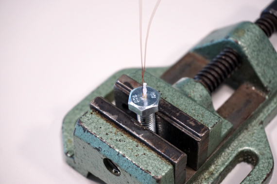
The use of optical fiber sensors for tightening control represents an advanced technical solution, leveraging the unique properties of optical transmission to ensure precise measurement of stresses exerted on bolts within an assembly. This method involves inserting an optical fiber into the bolt body, forming a Bragg network.
Integrating optical fiber requires drilling into the bolt, which slightly reduces its structural integrity and consequently its overall strength. Due to this alteration, it is crucial to thoroughly assess the potential impact on the mechanical performance of the assembly. Moreover, some feedback indicates that installing this type of system can be more complex compared to conventional tightening methods.
Without delving further into details, it is important to note that this bolt tightening technique is both intrusive and costly. The complexity of implementation and the associated expense of using optical fiber to measure tightening stresses make this approach less suitable for industrial applications. However, the precision and reliability advantages may justify its use in laboratory testing contexts.
It is evident that traditional methods of bolt tightening control are often intrusive or present various issues that hinder their direct use in industrial settings. These bolt tightening techniques, typically suited for laboratory and experimental environments, are less reproducible in real-world situations and unsuitable for the pace of industrial production. Nonetheless, the ultrasonic method utilized by TRAXX systems presents an innovative and effective solution to overcome these challenges.

Ultrasonic bolt load measurement
Principle of the bolt tightening method
We now turn to the ultrasonic bolt load measurement method, notably employed by TRAXX systems. This method relies on a fairly straightforward concept: sending an ultrasonic wave into the bolt. The wave propagates through the bolt to its end, where it undergoes a half-turn.
Ultrasonic waves, being mechanical waves, require a material medium to propagate and cannot travel through air. TRAXX systems utilize very high-frequency ultrasonics, typically in the range of 10 to 15 megahertz, for this application.
The key principle is to measure the time of flight of the ultrasonic waves — that is, the time taken for the wave to travel to the end of the bolt and back. Here’s how it works:
- Initial measurement: initially, the time of flight of ultrasonics is measured in a loose bolt.
- Measurement after tightening: subsequently, the time of flight is measured in the same bolt after tightening. Since the bolt elongates slightly when tightened, the ultrasonic wave takes longer for the round trip.
The difference between the initial time of flight ti and the final time of flight tf is denoted as Δt. This Δt variation is proportional to the tension present in the bolt.
While the concept is straightforward, precision is critical. The bolt elongates only by a few microns, necessitating time of flight measurements with a resolution on the order of nanoseconds.
To determine the tension in the bolt, the following relationship is used:
T (tension in N) = K (N/ns) x ∆t (ns)
The K coefficient is specific to each batch of bolts and must be determined experimentally. Instead of calculating this coefficient theoretically, TRAXX systems undergo a practical characterization phase: a series of measurements are conducted on a representative sample of bolts to establish the value of K.

Characterization phase
The characterization phase is crucial and is conducted only once for each batch of bolts. Here is the detailed procedure:
Preparation: Select a representative bolt from the batch.
Application of forces: Subject the bolt to increasing forces using a tensile testing machine (e.g., 5 kN, 10 kN, 25 kN, 50 kN).
Ultrasonic measurement: Place the ultrasonic transmitter/receiver on the head of the bolt. At each applied force level, measure the elongation of the ultrasonic time of flight.
Creation of correspondence table: Record the applied tensions and corresponding times of flight, creating a correspondence table.
Determination of coefficient K: Plot a graph with the measured elongations in nanoseconds on the x-axis and the tensions in kilonewtons on the y-axis. The slope of this line is the coefficient K.
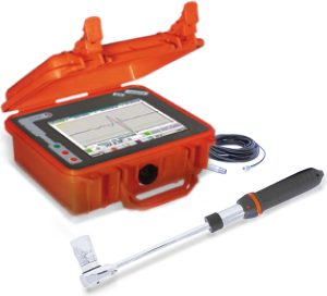
Once the coefficient K is determined, you can quickly and accurately measure the tension of a tightened bolt in an assembly. Simply place the ultrasonic transmitter/receiver on the head of the bolt with some coupling gel, and the measurement is displayed instantly on the TRAXX device.
This bolt tightening method is compatible with all types of bolts, whether they measure from 2 cm to 14 m in length, have a diameter of 3 mm to 300 mm, and are made from various materials. One of the main advantages of the TRAXX system is that it works on unprepared and unmodified bolts: raw bolts. You only need to place the sensor on the head of the bolts, and the device does the rest.

Sources of uncertainty in this type of tightening method
The main causes of uncertainty are external to the TRAXX system and include:
Variability of coefficient K: This variability arises from manufacturing discrepancies within the same batch of bolts. By characterizing several bolts from a batch, a representative coefficient K for the entire batch can be determined.
Accuracy of the tensile testing machine: The uncertainty of the tensile testing machine used during the characterization phase can affect the results, with a margin of error of ±1 to 2%.
Condition of the bolt: In very specific cases, the condition of the bolt can influence the measurement. Factors such as surface roughness, corrosion, and previous mechanical stress can play a role.
Placement of the sensor: Careless placement of the sensor on the bolt by the operator can slightly affect the measurement. Ensuring consistent and correct sensor placement is crucial for accurate readings.
We are aware of these external factors and know how to quantify them. By accounting for all uncertainties, this method allows for achieving an accuracy better than 5% on the actual tension, and up to 1 to 2% under optimal conditions. This makes the TRAXX system a highly reliable tool for precise bolt tension measurements in various industrial applications.
When to use a TRAXX system?
TRAXX systems are extremely versatile and prove useful in numerous scenarios:
Measurement during tightening:
TRAXX devices enable real-time tension measurement of a bolt during the tightening process. This means that while using the traditional torque tightening method, you can rely on the results displayed by the TRAXX system rather than those indicated by the torque wrench. This ensures greater accuracy in controlling the applied tension.
Assembly monitoring over time:
TRAXX systems can record the state of the bolts during the initial assembly. This feature allows for subsequent checks to determine if an assembly has loosened over time or due to a specific event. Furthermore, real-time use while the assembly is in service enables direct observation of tension variations under different operating conditions.
Expertise and Diagnostics:
TRAXX systems are also valuable for inspections and diagnostics. For instance, if a joint in an assembly fails and there is suspicion of a tightening issue, you can measure the current tension of the concerned bolts. Then, by loosening the bolt, you can measure its initial state to determine the previous tension and identify the problem. This diagnostic capability is particularly useful and frequently employed.
In summary, TRAXX systems enhance precision and reliability in various stages of bolt tightening and monitoring. Whether used during initial assembly, for ongoing monitoring, or for diagnostic purposes, TRAXX systems provide valuable insights and ensure that the correct tension is consistently applied and maintained. This makes them indispensable tools in industrial applications where accurate bolt tensioning is critical.
Comparison with other ultrasonic bolt tightening method
There are two other ultrasonic measurement methods, but they have notable disadvantages compared to the TRAXX system:
1. Instrumented bolts with piezoelectric sensors
This method operates on a principle similar to the TRAXX system but requires the installation of a three-layer sensor on the head of the bolt. This involves meticulous cleaning, permanent vacuum installation, and high costs for each modified bolt.
2. Instrumented bolts with permanent sensors
This method integrates a sensor directly into the body of the bolt during manufacturing. Although precise, this process is very expensive as it requires the production of special bolts. Each sensor must then be connected to a measurement probe to obtain results.
In conclusion, TRAXX systems provide accurate results without requiring modifications to the bolts in an assembly. This capability to deliver reliable measurements with standard bolts makes it a preferred solution in many industrial and technical contexts.